PART 3 of How to replace damaged bearings on a precision CNC spindle
Installing Angular Contact Bearing and Preload
This is the third in a five part series of tips and suggestions for replacing bearing in a precision CNC spindle. This series is specifically for the DIY person with limited resources. It is not a comprehensive description of how a fully equipped shop that specialized in spindle repair works. While we will reference certain specific spindle makes it is primarily intended to be rather generic. If you have a specific question please send an email at [email protected] or call 1-603-483-0333.
In the previous two blogs we considered some tips on getting your spindle apart. We also considered some points concerning Angular Contact Bearings and lubrication. This week we’ll discuss the different configurations for Angular Contact Bearings and how preload is accomplished.
Angular Contact Bearing Configurations
Spindles employ many different bearing configurations depending on the engineering requirements. But as a minimum they need at least two Angular Contact Bearings (ACB) installed in opposite directions to handle thrust loads. The most common arrangement is referred to as back to back or DB. As the name implies the back side of the bearings are facing each other.

Back to Back with a Tandem element or DBD

Back to Back or DB
By adding one or more bearings in tandem arrangement the thrust and radial load capacities along with axial stiffness can be increased. Most ACB arrangements in high speed spindles are a derivative or variation of back to back and tandem assemblies. There may be spacers in-between the individual bearings. There may be multiple tandem sets that are back to back at opposite ends of the spindle. There may be a triple or quad set of tandem bearings. And spindles that see high radial loads may have a roller bearing thrown into the mix. Often a roller is found at the end of a long shaft on a milling spindle. Front to front bearing arrangements are very rare. Front to front arrangements are sometimes found where misalignment is a concern and these arrangements are not discussed in this blog series.
But no matter which arrangement your spindle has, it’s important to keep track of the order of the bearing stack as it comes apart. Worth repeating is to make sure you keep inner and out spacer sets together. These should not be mixed and matched.
Setting Proper Preload for Angular Contact Bearings
Proper angular bearing preload is critical for proper spindle operation. Preload is required to give the spindle rigidity. Insufficient preload and the part finish will suffer leaving chatter marks or rough surface finish. Too much preload and the spindle will overheat and bearing life will be greatly reduced.
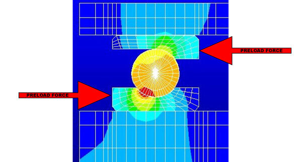
This FEA shows the stress induced by axial preload on an ACB.
Precision spindles mostly use two types of preload; rigid and constant or spring preload. We read a lot about preload on the forums and there is a bit of misinformation. For ACBs, preload is specified in the bearing nomenclature and determined by how the races are ground at the factory. Almost all high speed spindles use light or extra light preload. However, preload can be changed and adversely affected by a number of factors including:
- Thermal expansion or contraction
- Centrifugal forces at high speeds
- Deformation causes by excessive capture
- Deformation caused by excessive tightening of the shaft nut
- Radial dimensions of the shaft or housing
- Spring fatigue (compliant preload)
- Mismatched spacers
It is beyond the scope of this discussion to speak about all of various considerations that affect preload. But we do want to explain how preload is set for the majority of spindles that the DIYer is likely to encounter. While there are some special rare cases where the preload may need adjustment. Our first preload recommendation is to stay with the factory designed preload.
How Is Rigid Factory Preload Accomplished?
ACBs are preloaded in the axial direction. Specified bearing preload is determined by how the races are ground. When all of the balls are just making contact with both race surfaces there will be a slight offset between the face of the inner and outer race. When properly installed and that offset is at zero the bearings are preloaded to the factory specification.

The preload is called out in the bearing part number and set by the manufacturing process. The spindle re-builder should stick with that.
When bearings are arranged back to back (DB) on a shaft they can be preloaded without being installed into a housing. In the simple illustration below the inner races are held tight between the shoulder on the shaft and the lock nut. Because the bearings are back to back the offset is zeroed out on both bearings and the bearings are at factory preload. This is a rigid preload.

Rigid Preload Example of Basic Back to Back (DB) bearing arrangement. Note that rigid preload for back to back bearings is set on the shaft.
This diagram also illustrates the need to have precision lock nuts and precision ground shoulders. If they have high spots or if they are not square and perpendicular to the axis of rotation the bearings will experience misalignment and race deformation. This is detectable by examining the vibration spectrum and may manifest itself as excessive run-out.
To achieve a higher capacity to resist overturning loads many bearing arrangements include spacers to spread the bearing centerline distance. The spacers will be a set; one inner and one outer spacer. To keep bearing preload at the designated factory setting, the spacers must be match ground. That is, they need to be the same length. And perhaps even more importantly they need to be square and parallel.

Angular Contact Bearings Mounted Back to Back with a Spacer
This illustrates a simple back to back bearing arrangement with a spacer set. Note that the bearings are fully preloaded on the shaft. Both spacers must be match ground to within a few microns to achieve factory preload. If the outer spacer is smaller than the inner the preload will be less. If the outer spacer is larger the preload will be higher. Both conditions will change the stiffness (plus or minus) of the spindle and reduce the life expectance of the bearings.
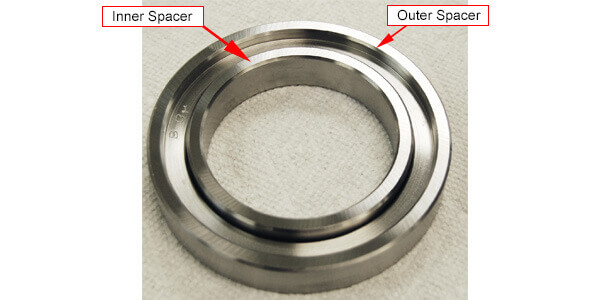
Spacers Help Performance but Must be Match Ground
If you need more stiffness because of a particular job you can grind the inner spacer a few 10ths smaller to achieve a medium preload. Bearing manufacturers publish that data or at least the formulas needed to determine the dimension to preload ratio. Be aware that you will sacrifice bearing life.
To keep spacers the same length we match grind them on our cup wheel grinder. Then they are carefully checked to make sure they are parallel.
With care, spacers can be hand lapped. We often do the last few microns by hand. But frequent checks at multiple spots with a good micrometer are required to make sure spacers are staying parallel.
Spring Preload
Spring preload also called constant or compliant preload uses a spring pack arrangement to apply bearing preload. Spring preload has the advantage of maintaining a relatively constant bearing preload and compensating for thermal expansion and to some extent centrifugal forces. Spring preload is commonly found in high speed grinding spindles. And Franz Kessler spindles often employ rather elaborate and effective spring load arrangements at both ends of their spindles.

Many grinding and routing spindles employ a basic spring pack arrangement to maintain constant bearing preload.
A typical spring pack consists of a stationary cage that usually reacts against the housing bore in some fashion, a bunch of springs and a movable spring cage that pushes against the outer race of a particular bearing.
If your spindle is spring preloaded, replace all of the springs when replacing the bearings. There are a number of good spring manufacturers and they can help you match the existing springs. Order 30 – 40% more springs than needed and check the length of each spring. Then group them according to length. Discard the most deviant springs. Nothing should be more than 1-2% from mean. Arrange similar length springs 180o from each other.

A basic grinding spindle with spring preload. Notice that the one spring pack preloads all four bearings. This allows for thermal expansion without significant change in bearing preload.
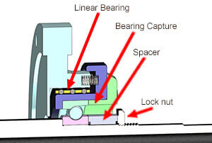
The design shown above requires clearance between the bearing and spacer stack and the inside of the spindle housing. This can affect spindle performance. To gain the advantages of a spring preload and a zero clearance fit some manufacturers use a linear bearing arrangement.
Linear bearings come in many shapes and sizes. They allow for smooth axial translation with zero clearance. These should be rebuilt at the same time the bearings are replaced. Carefully measure several ball diameters with a good micrometer. There are a number of vendors that sell hardened high precision balls. Order extra.

This linear ball bearing race is from a Franz Kessler spindle.
Note the preload springs around the periphery.
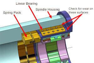
Some routing spindles such Boneham Turner use a linear bearing arrangement combined with a spring pack similar to the one illustrated here. If your spindle utilizes this arrangement check the surfaces that the linear bearing rides on. These can become worn and require surface restoration through a GPG process.
Typical back end spring preload arrangement for a Franz Kessler spindle
One manufacturer of high end milling spindles that makes extensive use spring preload is Franz Kessler. In fact, FK spindles often utilize a spring preload in the front and back of the spindle. This helps to compensate for any misalignment and allows their spindles to run very fast and very smooth. However, Franz Kesslers can be a relatively complicated spindle. Unless you have some experience we do not recommend repairing these on your own.
Take aways:
- Do not transfer installation forces through the rolling elements.
- Angular contact bearings have a front and back. Be careful to install them in the correct position.
- If the spindle is spring preloaded replace all springs with the bearings.
- Take lots of photos.
Please send us your comments, suggestions our questions.
Next week we’ll talk about Cylindrical Roller Bearings.
PART 3 of How to replace damaged bearings on a precision CNC spindle
Installing Angular Contact Bearing and Preload
This is the third in a five part series of tips and suggestions for replacing bearing in a precision CNC spindle. This series is specifically for the DIY person with limited resources. It is not a comprehensive description of how a fully equipped shop that specialized in spindle repair works. While we will reference certain specific spindle makes it is primarily intended to be rather generic. If you have a specific question please send an email at [email protected] or call 1-603-483-0333.
In the previous two blogs we considered some tips on getting your spindle apart. We also considered some points concerning Angular Contact Bearings and lubrication. This week we’ll discuss the different configurations for Angular Contact Bearings and how preload is accomplished.
Angular Contact Bearing Configurations
Spindles employ many different bearing configurations depending on the engineering requirements. But as a minimum they need at least two Angular Contact Bearings (ACB) installed in opposite directions to handle thrust loads. The most common arrangement is referred to as back to back or DB. As the name implies the back side of the bearings are facing each other.
Back to Back with a Tandem element or DBD
Back to Back or DB
By adding one or more bearings in tandem arrangement the thrust and radial load capacities along with axial stiffness can be increased. Most ACB arrangements in high speed spindles are a derivative or variation of back to back and tandem assemblies. There may be spacers in-between the individual bearings. There may be multiple tandem sets that are back to back at opposite ends of the spindle. There may be a triple or quad set of tandem bearings. And spindles that see high radial loads may have a roller bearing thrown into the mix. Often a roller is found at the end of a long shaft on a milling spindle. Front to front bearing arrangements are very rare. Front to front arrangements are sometimes found where misalignment is a concern and these arrangements are not discussed in this blog series.
But no matter which arrangement your spindle has, it’s important to keep track of the order of the bearing stack as it comes apart. Worth repeating is to make sure you keep inner and out spacer sets together. These should not be mixed and matched.
Setting Proper Preload for Angular Contact Bearings
Proper angular bearing preload is critical for proper spindle operation. Preload is required to give the spindle rigidity. Insufficient preload and the part finish will suffer leaving chatter marks or rough surface finish. Too much preload and the spindle will overheat and bearing life will be greatly reduced.
This FEA shows the stress induced by axial preload on an ACB.
Precision spindles mostly use two types of preload; rigid and constant or spring preload. We read a lot about preload on the forums and there is a bit of misinformation. For ACBs, preload is specified in the bearing nomenclature and determined by how the races are ground at the factory. Almost all high speed spindles use light or extra light preload. However, preload can be changed and adversely affected by a number of factors including:
- Thermal expansion or contraction
- Centrifugal forces at high speeds
- Deformation causes by excessive capture
- Deformation caused by excessive tightening of the shaft nut
- Radial dimensions of the shaft or housing
- Spring fatigue (compliant preload)
- Mismatched spacers
It is beyond the scope of this discussion to speak about all of various considerations that affect preload. But we do want to explain how preload is set for the majority of spindles that the DIYer is likely to encounter. While there are some special rare cases where the preload may need adjustment. Our first preload recommendation is to stay with the factory designed preload.
How Is Rigid Factory Preload Accomplished?
ACBs are preloaded in the axial direction. Specified bearing preload is determined by how the races are ground. When all of the balls are just making contact with both race surfaces there will be a slight offset between the face of the inner and outer race. When properly installed and that offset is at zero the bearings are preloaded to the factory specification.
The preload is called out in the bearing part number and set by the manufacturing process. The spindle re-builder should stick with that.
When bearings are arranged back to back (DB) on a shaft they can be preloaded without being installed into a housing. In the simple illustration below the inner races are held tight between the shoulder on the shaft and the lock nut. Because the bearings are back to back the offset is zeroed out on both bearings and the bearings are at factory preload. This is a rigid preload.
Rigid Preload Example of Basic Back to Back (DB) bearing arrangement. Note that rigid preload for back to back bearings is set on the shaft.
This diagram also illustrates the need to have precision lock nuts and precision ground shoulders. If they have high spots or if they are not square and perpendicular to the axis of rotation the bearings will experience misalignment and race deformation. This is detectable by examining the vibration spectrum and may manifest itself as excessive run-out.
To achieve a higher capacity to resist overturning loads many bearing arrangements include spacers to spread the bearing centerline distance. The spacers will be a set; one inner and one outer spacer. To keep bearing preload at the designated factory setting, the spacers must be match ground. That is, they need to be the same length. And perhaps even more importantly they need to be square and parallel.
Angular Contact Bearings Mounted Back to Back with a Spacer
This illustrates a simple back to back bearing arrangement with a spacer set. Note that the bearings are fully preloaded on the shaft. Both spacers must be match ground to within a few microns to achieve factory preload. If the outer spacer is smaller than the inner the preload will be less. If the outer spacer is larger the preload will be higher. Both conditions will change the stiffness (plus or minus) of the spindle and reduce the life expectance of the bearings.
Spacers Help Performance but Must be Match Ground
If you need more stiffness because of a particular job you can grind the inner spacer a few 10ths smaller to achieve a medium preload. Bearing manufacturers publish that data or at least the formulas needed to determine the dimension to preload ratio. Be aware that you will sacrifice bearing life.
To keep spacers the same length we match grind them on our cup wheel grinder. Then they are carefully checked to make sure they are parallel.
With care, spacers can be hand lapped. We often do the last few microns by hand. But frequent checks at multiple spots with a good micrometer are required to make sure spacers are staying parallel.
Spring Preload
Spring preload also called constant or compliant preload uses a spring pack arrangement to apply bearing preload. Spring preload has the advantage of maintaining a relatively constant bearing preload and compensating for thermal expansion and to some extent centrifugal forces. Spring preload is commonly found in high speed grinding spindles. And Franz Kessler spindles often employ rather elaborate and effective spring load arrangements at both ends of their spindles.
Many grinding and routing spindles employ a basic spring pack arrangement to maintain constant bearing preload.
A typical spring pack consists of a stationary cage that usually reacts against the housing bore in some fashion, a bunch of springs and a movable spring cage that pushes against the outer race of a particular bearing.
If your spindle is spring preloaded, replace all of the springs when replacing the bearings. There are a number of good spring manufacturers and they can help you match the existing springs. Order 30 – 40% more springs than needed and check the length of each spring. Then group them according to length. Discard the most deviant springs. Nothing should be more than 1-2% from mean. Arrange similar length springs 180o from each other.
A basic grinding spindle with spring preload. Notice that the one spring pack preloads all four bearings. This allows for thermal expansion without significant change in bearing preload.
The design shown above requires clearance between the bearing and spacer stack and the inside of the spindle housing. This can affect spindle performance. To gain the advantages of a spring preload and a zero clearance fit some manufacturers use a linear bearing arrangement.
Linear bearings come in many shapes and sizes. They allow for smooth axial translation with zero clearance. These should be rebuilt at the same time the bearings are replaced. Carefully measure several ball diameters with a good micrometer. There are a number of vendors that sell hardened high precision balls. Order extra.
This linear ball bearing race is from a Franz Kessler spindle.
Note the preload springs around the periphery.
Some routing spindles such Boneham Turner use a linear bearing arrangement combined with a spring pack similar to the one illustrated here. If your spindle utilizes this arrangement check the surfaces that the linear bearing rides on. These can become worn and require surface restoration through a GPG process.
Typical back end spring preload arrangement for a Franz Kessler spindle
One manufacturer of high end milling spindles that makes extensive use spring preload is Franz Kessler. In fact, FK spindles often utilize a spring preload in the front and back of the spindle. This helps to compensate for any misalignment and allows their spindles to run very fast and very smooth. However, Franz Kesslers can be a relatively complicated spindle. Unless you have some experience we do not recommend repairing these on your own.
Take aways:
- Do not transfer installation forces through the rolling elements.
- Angular contact bearings have a front and back. Be careful to install them in the correct position.
- If the spindle is spring preloaded replace all springs with the bearings.
- Take lots of photos.
Please send us your comments, suggestions our questions.
Next week we’ll talk about Cylindrical Roller Bearings.